
Assembling Voron Tap #
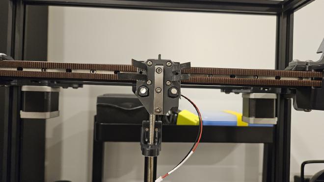
The standard method for homing the z-axis on a Trident uses an inductive probe. The Formbot kit, however, includes the parts for Voron Tap. Voron Tap adds a linear rail, some magnets, and an optical sensor (most common setup but there are alternatives) to the x-axis carriage, allowing the toolhead to probe the bed by tapping it with the nozzle.
My kit came with parts for Revision 8 which includes some changes to the printed parts and requires some more hardware to assemble compared to previous versions.
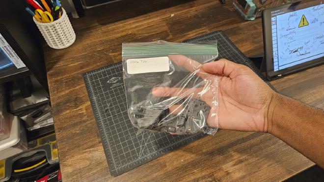
Assembly for Voron Tap involves adding heat-set inserts to the printed parts, installing some captive nuts, and mounting some electronics. The Formbot kit comes with the OptoTap sensor so you’ll want to make sure you print the correct parts for that as well.
During assembly, make sure you follow both the pdf manual and the R8 markdown file instructions in the GitHub repo. I missed the RC8 specific instructions the first time around and had to go back and add the remaining bits of hardware. But once you’ve done that you’ll be left with two different printed assemblies that are ready to be mounted to your Trident.
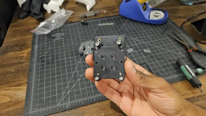
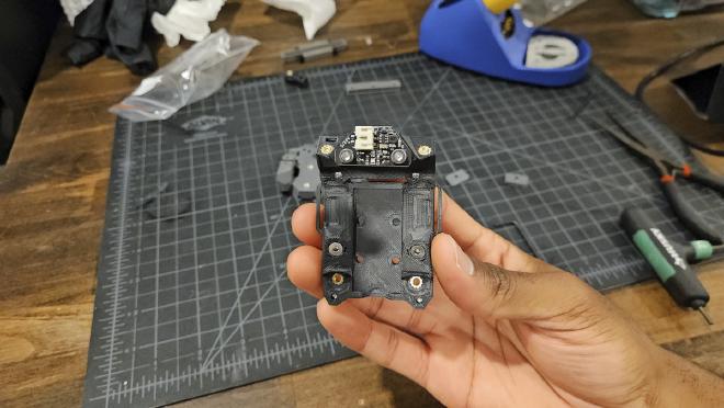
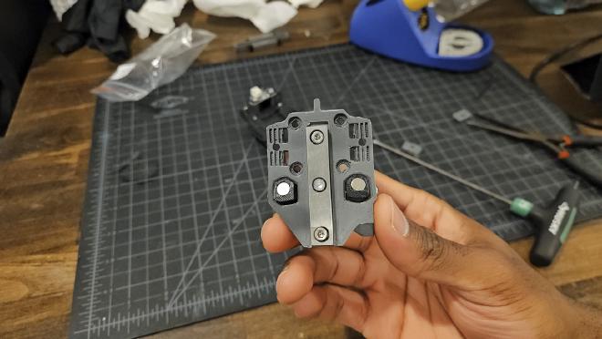
These parts will be used in place of the default x-carriage parts for the Trident, so no need to print those out.
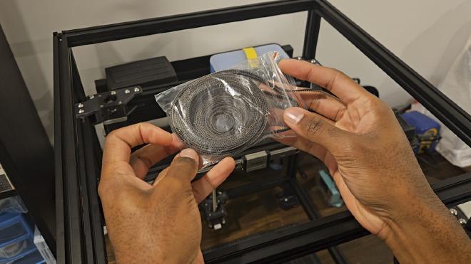
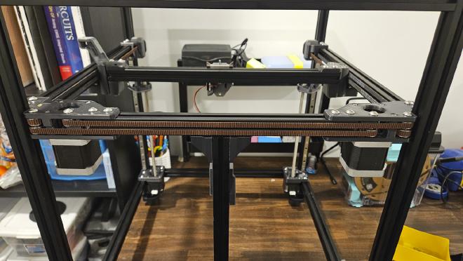
Running the XY Belts #
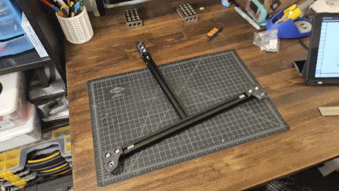
Now that the Voron Tap parts are assembled, I can start the belt assembly. The Formbot kit includes 2 6mm GT2 belts of equal length. It was super-helpful to have two separate belts instead of one long belt, I personally think it makes things easier to setup.
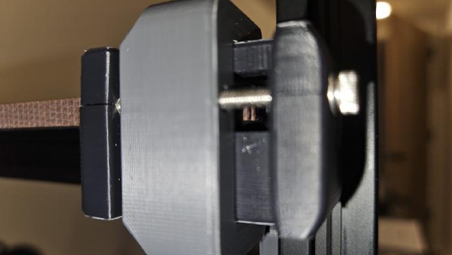
Before running the belts you’ll want to make sure that the two front idlers are fully loosened. It’ll make it easier to feed the belts through them and onto the GT2 pulleys inside.
Since the two belts need to be the same length, you’ll want to run the first belt and cut it down to size. Then you’ll take the second belt and cut it to match.
If you’re unfamiliar with the way the CoreXY belts are run in a Trident, I would actually recommend a “dry-run” install first. I did this with both belts to make sure I fully understood the paths for each belt before cutting them. Just make sure you don’t run them too tight or you’ll end up racking your gantry.
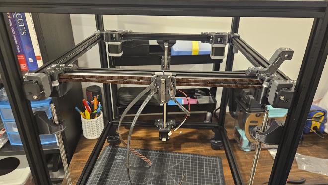
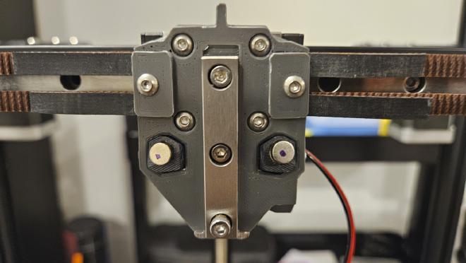
To get the correct length for the first belt, I installed the Voron Tap carriage and inserted one end of the belt into the carriage. I started with the top belt and left about 1.5" of belt sticking out. Once I ran the first belt, I then marked the same 1.5" on the other side.
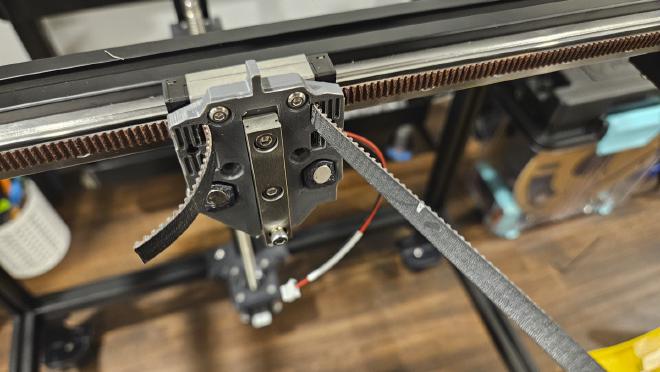
Then I removed the belt and cut it at the mark I made. The second belt was also cut to match the length of the first. If you’re following along and assuming you got your measurements correct, when you go to run both belts you should have about 1.5" of belt on each side of the carriage.
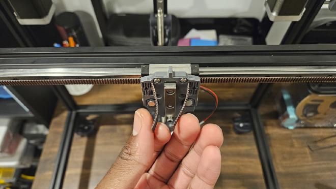
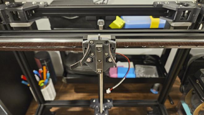
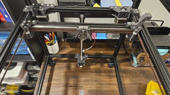
At this point I didn’t bother tensioning the belts or installing the other Voron Tap part because I wanted to wait until the toolhead was assembled so I could do it all in one go. So for now I just installed the belt clips to secure the belts and move them out of the way so I could move on to the bed install.
Print Bed Prep #
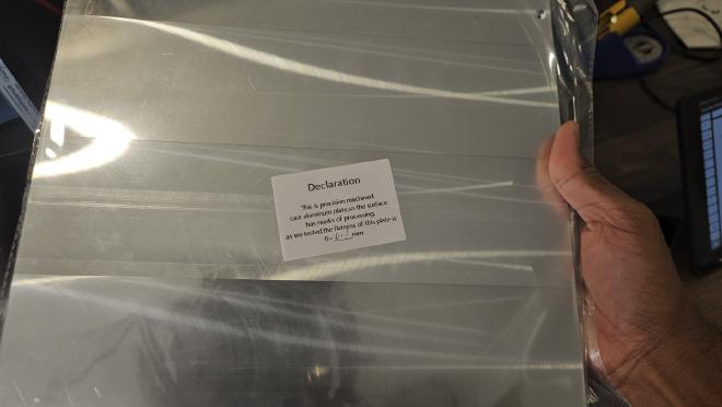
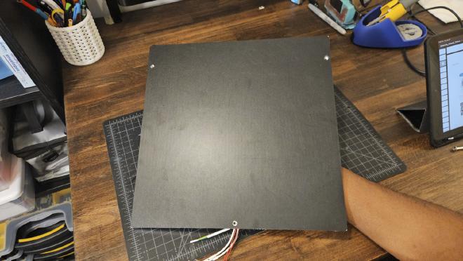
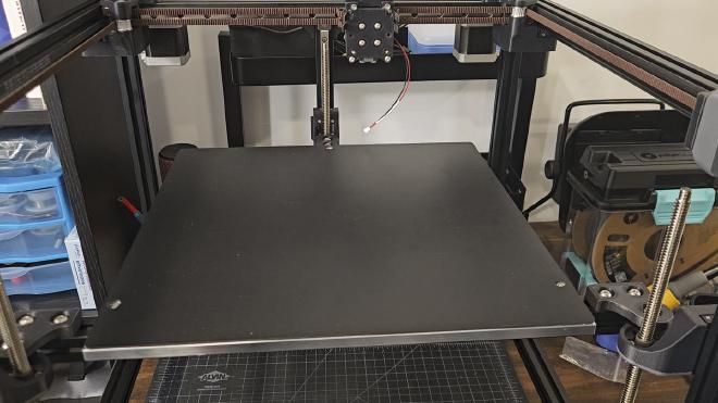
The print bed included with the Formbot kit is a 5/16" thick cast aluminum plate. According to Formbot, this bed plate should be mostly flat with a margin of error between 0-0.1mm.
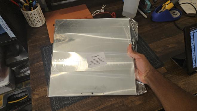
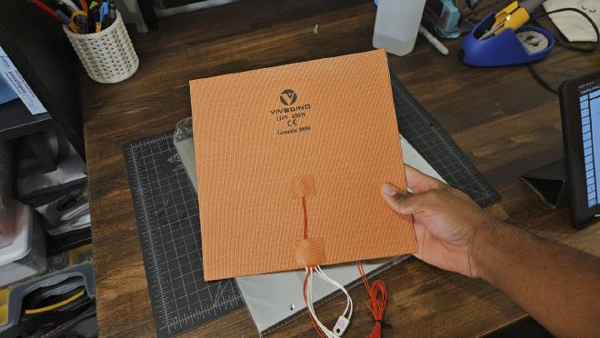
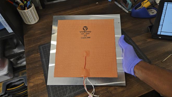
The bed heater is a Vivedino 110V 450W silicone AC Heater. The heater comes with a built in thermistor and thermal fuse rated for 125°C.
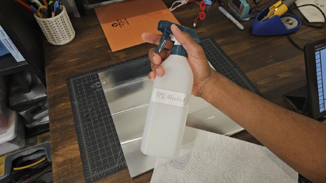
Before installing the bed on the Trident, the silicone heater and adhesive magnetic sheet need to be installed onto the bed first. Just like with the linear rails, you’ll want to thoroughly clean the bed off with some 91% Isopropyl alcohol.
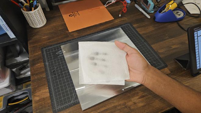
I’d recommend installing the magnetic sheet first while the bed can still lie flat on the table. I used a small plastic part removal tool to help get rid of any bubbles under the sheet. Once the adhesive was applied, I went back in with a craft knife and carefully removed the material blocking the screw holes on the bed.
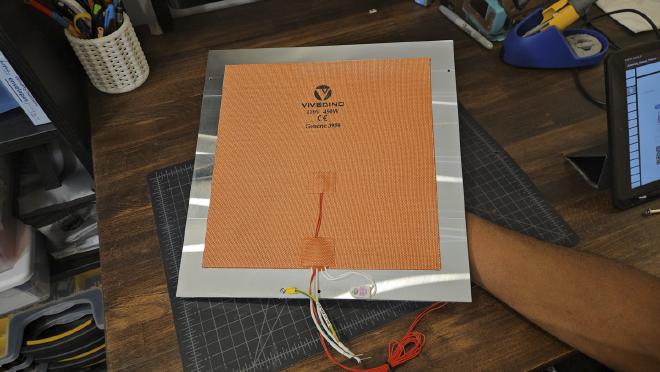
Then I flipped the bed over and followed the same application process for the bed heater, centering it as best I can. I’m not sure how effective this heater will be in warming the bed so I may consider replacing it with an edge-to-edge bed heater like this one from Fabreeko.
And while I was here, I also installed the ground wire and attached the thermal fuse to the bed.
Installing the Print Bed #
The install for the bed is pretty easy. First thing you need to do is get the WAGO connector piece ready and assemble the bed frame extrusions.
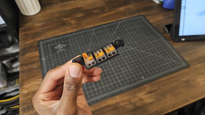
Then you just attach the bed frame assembly to the three z-carriages, mount the bed, and wire up the WAGO connectors.
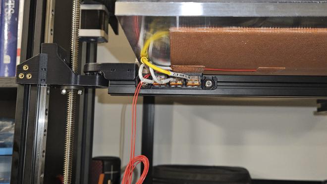
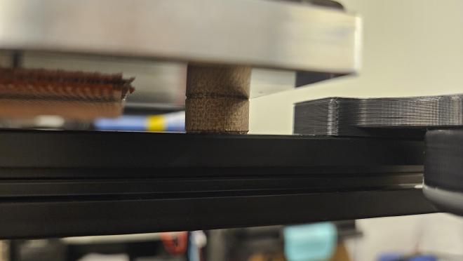
One interesting thing to note here is that instead of using thumb nuts for the bed install, the Formbot kit provides 3 Bakelite Isolation Columns to use instead. I think these should help with insulating the extrusions from the heat of the bed, but I’m not 100% sure if that’s accurate.
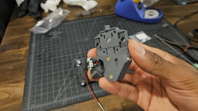
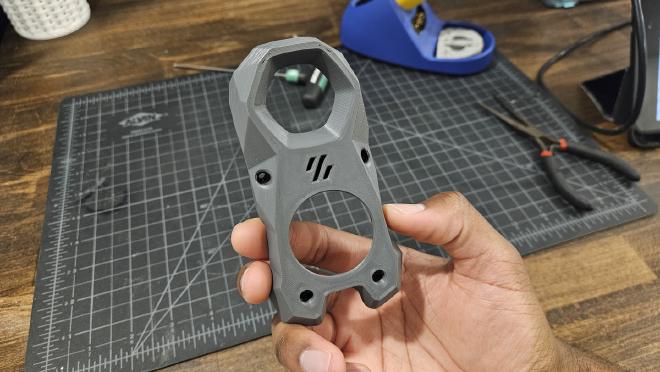
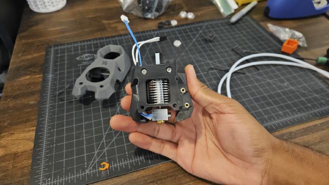
Building the Stealthburner #
At this point in the build, one of the last things left to do before moving on to the electronics is assembling the Stealthburner toolhead and mounting it to the x-carriage.
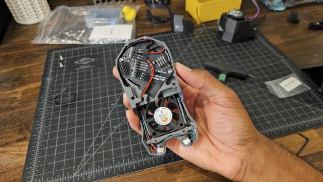
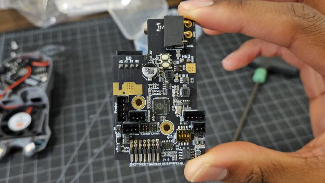
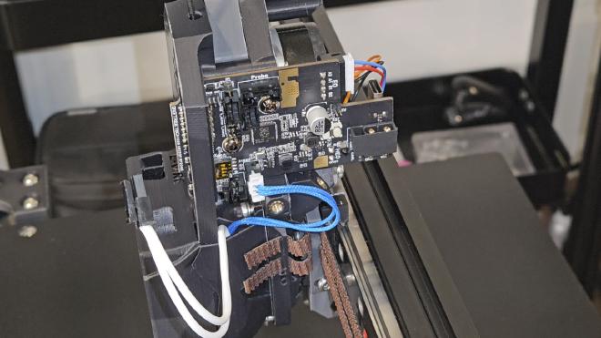
The Formbot kit includes the EBB 2209 (RP2040) toolhead board which will allow me to run a single CAN bus cable to the control board instead of needing a wiring harness with a bunch of wires. Most of the stealthburner printed parts are still the Voron default parts, except for a few that have been modified to allow the toolhead board to fit.
For the assembly, you’ll need to follow both the official Voron guide and the BTT EBB 2209 (RP2040) guide.
I learned this the hard way after assembling and mounting the entire toolhead only to realize that forgot to install the EBB 2209 board…

If you follow the correct set of instructions here, the assembly should be very straightforward.
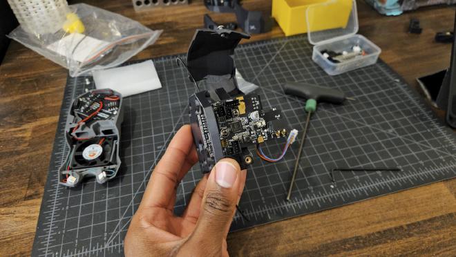
One thing to keep in mind is that the toolhead board has a set of jumpers and DIP switches that must be set correctly before powering things up. I took a first pass at getting everything set correctly here, but I’ll come back to this again when I setup the rest of the electronics. There are also a decent amount of jumpers to add to the main control board so it’ll be good to check everything together.
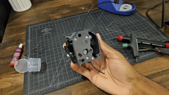
Installing the Toolhead #
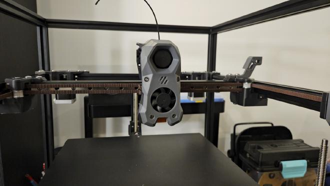
Mounting the toolhead to the x-carriage was simple, here you just want to follow the Voron Tap manual and make sure to properly align the Voron Tap magnets once everything is installed.
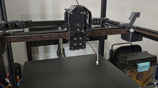
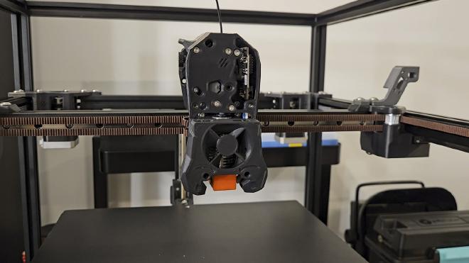
Now this is finally starting to look more like a 3D printer! And I have to say that I really love the look of the stealthburner toolhead, it’s a really cool piece of engineering.
Thanks for checking out this part of the build log! In the next build log I’ll be installing the electronics and wiring everything up, so stay tuned!