For Valentine’s Day last year, I wanted to create something special for my girlfriend to show her how much I cared about her. The pandemic had made it more difficult to see her as often as I used to, so I thought, what’s the best way to show her I care on a daily basis? That’s when I came up with the idea for the Emotion Lamp, an RGB lamp whose colors and patterns can be changed to signify different emotions or events. It was loosely based on those long-distance lamps you can buy from places like Amazon and Wish, but I knew from the start I wanted more control and flexibility than I could get from these devices.
I wanted the lamp to have the following features:
- Full RGB color spectrum with customizable patterns
- Capacitive touch button on the top of the lamp to turn it on/off and send commands to pair lamp
- Simple design that’s fully 3D-Printed for easy prototyping and replication
- Companion app for setting colors and patterns on lamp
Components #
Once I knew what I wanted to build, it was time to start sourcing components. Since I wanted this to be a long-distance lamp, I opted for the ESP8266 as the microcontroller for this project, specifically the Wemos D1 Mini variant. The built-in Wi-Fi and generous pinouts were more than enough for a project like this. For the RGB lights, I went with a strip of Neopixel LEDs (WS2812B) since they’re super easy to control using the FastLED library. And the last component is the capacitive touch sensor, I went with the TTP223 since it was readily available through Amazon.
Here’s the final list of supplies I used for this project:
- Wemos D1 Mini (ESP8266 breakout board)
- WS2812B LED Strip 1m (3.3ft) 60leds Individually Addressable (Generic Neopixels)
- TTP223 Capacitive Touch sensor
- JST-SM connectors for LED strips (optional but highly recommended)
- DC 5.5mm Power Jack Socket
- SPST 6A/125V Power Switch
- 5V 4A Power Supply
- 22 AWG wire for signal connections
- 16 AWG wire for power connection
- 470 Ohm resistor
- Any color PLA filament (for the stand)
- Transparent PLA filament (might be able to get away with white but I haven’t tried it)
- M3 threaded inserts (optional)
If you’re assembling the lamp using the custom PCB I designed, you’ll also need:
- 3-pin screw terminal
- 2-pin screw terminal
- Male & Female Headers
You can find the exact list of everything I used for this project will be at the end of this post.
Once you have the components, you’ll need to begin printing out the enclosure for the lamp. If you want a better-looking lamp, at the cost of more time during assembly, you should print out the following parts:
EmotionLamp_Bottom_Stand_no_Inserts.stlorEmotionLamp_Bottom_Stand_with_Inserts.stlEmotion_Lamp_LED _Stand_Strip.stlEmotion_Lamp_Transparent_Cover.stl
If you’d rather not spend that extra time then this is what you need to print:
EmotionLamp_Bottom_Stand_no_Inserts.stlorEmotionLamp_Bottom_Stand_with_Inserts.stlEmotion_Lamp_LED_Stand_Spiral.stlEmotion_Lamp_Transparent_Cover.stl
For the bottom stand, you can print out either STL depending on whether or not you’re using M3 inserts.
I printed out everything on my Prusa i3 MK3S with the following settings:
- 0.3mm layer height
- 10% Infill, Grid pattern
- No supports
Software #
In order for the Emotion Lamp to work, you’ll need to set up an MQTT broker for the lamps to communicate with. If you’re planning on keeping the lamps on the same WIFI network then you could set up a broker on your local machine or a Raspberry Pi. If you’re planning on having the lamps separated by a large distance then you’ll need an offsite server for them to connect to. I used an AWS instance running Debian to accomplish that. For more information on setting up an MQTT broker, you can visit this link here. I found that site to be a great resource for getting things up and running. If you’d like to set up an AWS instance, you can find more information about that here. If you set up an AWS instance, I recommend making sure you enable broker authentication with a username and password, in addition to changing the default broker port.
The Arduino code for the Emotion Lamp is basically a state machine, with each of the states corresponding to the desired pattern for the lamp to display. The setup functions are pretty self-explanatory, they initialize the wifi connection and the MQTT broker connections along with setting up important pins and variables. The main loop keeps the lamp connected to wifi and the MQTT broker, checks the state of the touch button, and calls the lamp_loop() function.
void loop() {
  if (!client.connected()) {
    reconnect();
  }
  client.loop();

  bool isPressed = (digitalRead(BUTTON_PIN) == HIGH);
  touch_btn.tick(isPressed);
  lamp_loop();
}
The lamp_loop() function contains a bunch of switch-case statements that ensure the correct patterns are being displayed to the lamp on a state change.
void lamp_loop() {
  switch (lampState) {

    case OFF: {
        if (stateChange) {
          FastLED.clear();
          FastLED.show();
#ifdef DEBUG
          Serial.println("LED to off");
#endif
        }
        break;
      }

    case SOLID: {
        if (stateChange) {
          if (colorType == RGB_COLOR)
            fill_solid(leds, NUM_LEDS, CRGB(color1[0], color1[1], color1[2]));

          else if (colorType == HSV_COLOR)
            fill_solid(leds, NUM_LEDS, CHSV(color1[0], color1[1], color1[2]));

          FastLED.show();
#ifdef DEBUG
          Serial.println("LED to solid");
#endif
        }
        break;
      }

    case STRIPES: {
        if (stateChange) {
          stripes(STRIPE_WIDTH);
#ifdef DEBUG
          Serial.println("LED to stripes");
#endif
        }
        break;
      }

    case GRADIENT: {
        if (stateChange) {
          if (colorType == RGB_COLOR) {
#ifdef LED_STRIP
            fill_gradient_RGB(temp_leds, 0, CRGB(color1[0], color1[1], color1[2]), LEDS_PER_STRIP - 1, CRGB(color2[0], color2[1], color2[2]));
#endif
#ifdef LED_SPIRAL
            fill_gradient_RGB(leds, 0, CRGB(color1[0], color1[1], color1[2]), NUM_LEDS - 1, CRGB(color2[0], color2[1], color2[2]));
#endif
          }

          else if (colorType == HSV_COLOR) {
#ifdef LED_STRIP
            fill_gradient(temp_leds, LEDS_PER_STRIP, CHSV(color1[0], color1[1], color1[2]), CHSV(color2[0], color2[1], color2[2]), SHORTEST_HUES);
#endif
#ifdef LED_SPIRAL
            fill_gradient(leds, NUM_LEDS, CHSV(color1[0], color1[1], color1[2]), CHSV(color2[0], color2[1], color2[2]), SHORTEST_HUES);
#endif
          }
          applyToStrips();
          FastLED.show();
#ifdef DEBUG
          Serial.println("LED to gradient");
#endif
        }
        break;
      }

    case MOVING_GRADIENT: {
        unsigned long currentMillis = millis();
        if (currentMillis - prevWaveTime > waveInterval) {
          prevWaveTime = currentMillis;
          moving_gradient();
        }
        break;
      }

    case BREATHE: {
        static bool holdColor = false;
        unsigned long currentMillis = millis();

        if (!holdColor) {
          unsigned long interval = (color1[2] > 0) ? (breatheInterval / color1[2]) : 10;
          if (currentMillis - prevBreatheTime > interval) {
            prevBreatheTime = currentMillis;
            holdColor = breathe(stateChange);
          }
        } else {
          if (currentMillis - prevBreatheTime > breatheHoldInterval) {
            prevBreatheTime = currentMillis;
            holdColor = breathe(stateChange);
          }
        }

        break;
      }

    case RAINBOW: {
        if (stateChange || (rainbowCycleCount >= RAINBOW_MAX_VALUE)) {
          rainbowCycleCount = 0;
        }
        unsigned long currentMillis = millis();
        if (currentMillis - prevRainbowTime > rainbowInterval) {
          prevRainbowTime = currentMillis;
          rainbow();
          rainbowCycleCount++;
        }
        break;
      }

    default: {
        break;
      }
  }
  stateChange = false;
}
The callback() function also contains a bunch of switch-case statements that process incoming JSON messages into state changes that then get handled by the lamp_loop().
void callback(char* topic, byte* payload, unsigned int length) {
#ifdef DEBUG
  Serial.print("Message arrived [");
  Serial.print(topic);
  Serial.println("] ");
#endif

  StaticJsonDocument<256> doc;
  DeserializationError error = deserializeJson(doc, payload, length);

  if (error) {
#ifdef DEBUG
    Serial.print(F("deserializeJson() failed: "));
    Serial.println(error.f_str());
#endif
    return;
  }

  if (doc["state"].is<int>()) {
    int newState = doc["state"];
    JsonObject color_doc = doc["color"];
    const char* color_type = color_doc["type"];
    JsonArray colors = color_doc["values"].as<JsonArray>();

    switch (newState) {
      // OFF
      case 0: {
          lampState = OFF;
          stateChange = true;
          break;
        }

      // SOLID
      case 1: {
          lampState = SOLID;
          JsonObject color = colors[0];

          if (strcmp(color_type, "rgb") == 0) {
            colorType = RGB_COLOR;
            color1[0] = color["r"];
            color1[1] = color["g"];
            color1[2] = color["b"];
          }
          else if (strcmp(color_type, "hsv") == 0) {
            colorType = HSV_COLOR;
            color1[0] = color["h"];
            color1[1] = color["s"];
            color1[2] = color["v"];
          }
          stateChange = true;
          break;
        }

      // STRIPES
      case 2: {
          lampState = STRIPES;
          JsonObject c1 = colors[0];
          JsonObject c2 = colors[1];

          if (strcmp(color_type, "rgb") == 0) {
            colorType = RGB_COLOR;
            color1[0] = c1["r"];
            color1[1] = c1["g"];
            color1[2] = c1["b"];
            color2[0] = c2["r"];
            color2[1] = c2["g"];
            color2[2] = c2["b"];
          }
          else if (strcmp(color_type, "hsv") == 0) {
            colorType = HSV_COLOR;
            color1[0] = c1["h"];
            color1[1] = c1["s"];
            color1[2] = c1["v"];
            color2[0] = c2["h"];
            color2[1] = c2["s"];
            color2[2] = c2["v"];
          }
          stateChange = true;
          break;
        }

      // GRADIENT
      case 3: {
          lampState = GRADIENT;
          JsonObject c1 = colors[0];
          JsonObject c2 = colors[1];

          if (strcmp(color_type, "rgb") == 0) {
            colorType = RGB_COLOR;
            color1[0] = c1["r"];
            color1[1] = c1["g"];
            color1[2] = c1["b"];
            color2[0] = c2["r"];
            color2[1] = c2["g"];
            color2[2] = c2["b"];
          }
          else if (strcmp(color_type, "hsv") == 0) {
            colorType = HSV_COLOR;
            color1[0] = c1["h"];
            color1[1] = c1["s"];
            color1[2] = c1["v"];
            color2[0] = c2["h"];
            color2[1] = c2["s"];
            color2[2] = c2["v"];
          }
          stateChange = true;
          break;
        }

      // MOVING GRADIENT
      case 4: {
          lampState = MOVING_GRADIENT;
          JsonObject c1 = colors[0];
          JsonObject c2 = colors[1];

          if (strcmp(color_type, "rgb") == 0) {
            colorType = RGB_COLOR;
            color1[0] = c1["r"];
            color1[1] = c1["g"];
            color1[2] = c1["b"];
            color2[0] = c2["r"];
            color2[1] = c2["g"];
            color2[2] = c2["b"];
            fill_gradient_RGB(gradient, 0, CRGB(color1[0], color1[1], color1[2]), GRADIENT_LENGTH - 1, CRGB(color2[0], color2[1], color2[2]));
          }
          else if (strcmp(color_type, "hsv") == 0) {
            colorType = HSV_COLOR;
            color1[0] = c1["h"];
            color1[1] = c1["s"];
            color1[2] = c1["v"];
            color2[0] = c2["h"];
            color2[1] = c2["s"];
            color2[2] = c2["v"];
            fill_gradient(gradient, 0, CHSV(color1[0], color1[1], color1[2]), GRADIENT_LENGTH - 1, CHSV(color2[0], color2[1], color2[2]), SHORTEST_HUES);
          }

          stateChange = true;
          break;
        }

      // BREATHE
      case 5: {
          lampState = BREATHE;
          JsonObject color = colors[0];

          if (strcmp(color_type, "rgb") == 0) {
            colorType = RGB_COLOR;
            color1[0] = color["r"];
            color1[1] = color["g"];
            color1[2] = color["b"];
          }
          else if (strcmp(color_type, "hsv") == 0) {
            colorType = HSV_COLOR;
            color1[0] = color["h"];
            color1[1] = color["s"];
            color1[2] = (color["v"] == 0) ? 10 : color["v"];
          }
          stateChange = true;
          break;
        }

      // RAINBOW
      case 6: {
          lampState = RAINBOW;
          stateChange = true;
          break;
        }

      default: {
          stateChange = false;
          break;
        }
    }
  }
}
If you’re not interested in modifying the main code, then you’ll only be concerned with the config_template.h file. To set up your lamp, you’ll need to copy this file and rename it config.h and then fill it in accordingly. Take note of the DEVICE_ID and PAIR_DEVICE_ID names, they’ll be reversed on the pair lamp. For example: if you set the DEVICE_ID of one lamp to Alpha and the PAIR_DEVICE_ID to Bravo, the other lamp would have its DEVICE_ID be Bravo and the PAIR_DEVICE_ID be Alpha.
// Copy this file and rename it config.h, then fill in your credentials

/******************************* WIFI **************************************/

#define WIFI_SSID       ""
#define WIFI_PASS       ""

/******************************* MQTT **************************************/

#define MQTT_BROKER     ""
#define MQTT_PORT       1883

// If MQTT broker is password protected, uncomment these lines and enter credentials
/*
#define MQTT_PROTECTED
#define MQTT_USERNAME   ""
#define MQTT_PASSWORD   ""
*/

#define MQTT_TOPIC_ROOT   ""

/******************************* DEVICE **************************************/

#define DEVICE_ID ""
#define PAIR_DEVICE_ID ""

// Uncomment one of these lines depending on the LED configuration
#define LED_STRIP
//#define LED_SPIRAL
If you wanted to modify the code to add additional patterns you would need to add a new case statement to lamp_loop() and callback() and also add an additional state to the lampStates enum at the top of the code.
There is an Android app available in the GitHub repo that will connect to the MQTT broker and give you a way to control both lamps directly and access the other patterns. The source code isn’t available yet but will be released at some point along with a more polished app (and maybe even an iOS app).
As of this code’s release on 2/25/22, I’m still working on cleaning it up a bit, there are a lot of #ifdef statements that I don’t particularly like. Once I clean it up I’ll update this page.
Assembly #
Circuit Assembly #
The first step is to assemble the circuit according to this schematic:
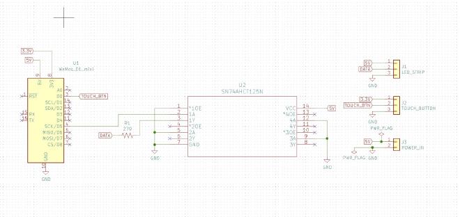
Emotion Lamp Schematic
If you’re using the custom PCB this step should be pretty easy, if you’re using perfboard it may take you a bit to plan out the layout and solder the right connections. Here are some photos of the finished circuit:
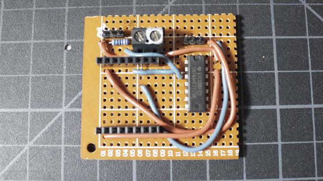
Finished Perfboard Circuit
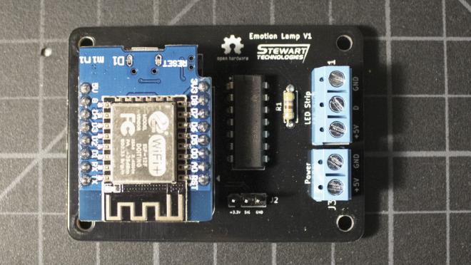
Finished PCB Circuit
Before moving forward you should test the circuit to make sure everything is working, upload the sketch to the microcontroller, and if everything’s working you should be able to use the capacitive touch button to control the lamp.
Enclosure Assembly #
Start by taking the bottom stand and inserting the M3 inserts into the 4 holes inside and the 3 on the outside (if you’re using them).
Next, you have to install and solder the power switch and power jack. Start by soldering wires to the positive and negative terminals of the power jack. Also, solder a wire to one of the terminals of the power switch. At this point, you should also heat-shrink the exposed solder joints or cover them with electrical tape.
Insert the power jack and power switch into the bottom stand and secure them in place (the jack has a nut to secure it, the switch is just press fit). Cut and solder the positive wire from the power jack onto the other terminal of the power switch, you should end up with something like this:
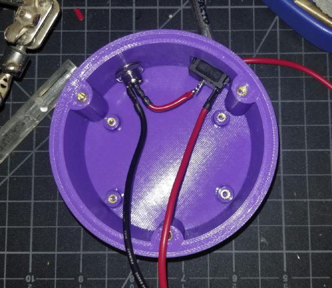
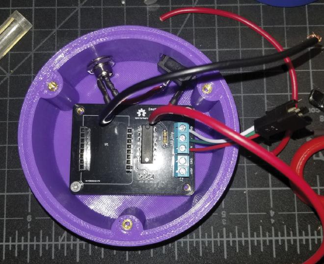
Power Wiring
Next, you’ll want to install the LED strips onto the 3D printed LED stand, if you’re going with the spiral configuration all you need to do is carefully wrap the strip around the center. If the strips have an adhesive backing, that should be enough to secure it in place, if it’s not you can use hot glue or zip ties like I did. The end result will look something like this:
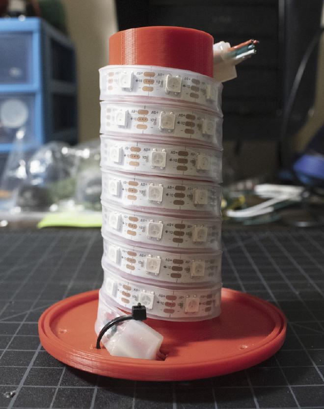
Spiral LED Configuration
If you’re going for the LED strip configuration you’ll need to cut the strip into 8 smaller strips, each with 6 LEDs on them (make sure you’re using the 60 LEDs/m strips). Secure each strip on the LED stand with the data lines alternating, there should be little arrows on the strip to indicate the direction of the data lines. Once all the strips are in place, you then have to solder the connections back together using some 22AWG wire. The end result will look something like this:
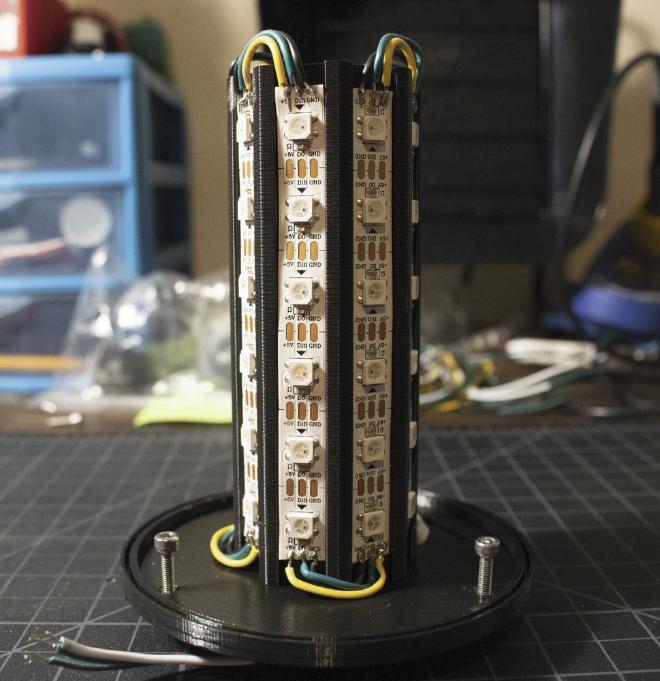
Strip LED Configuration
Last thing to do before the final assembly is to attach the capacitive touch button to the inside of the transparent cover. Solder on some male headers to the TTP223 and epoxy the button into place inside the cover (wouldn’t stay in place with just hot glue). It’ll look something like this:
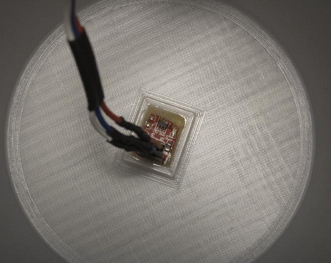
Touch Button Mount
Now that we have everything in place it’s time to put it together. Trim the wires in the bottom stand, insert them into the screw terminals on the PCB and then install the PCB into the bottom stand with some M3 4mm screws.
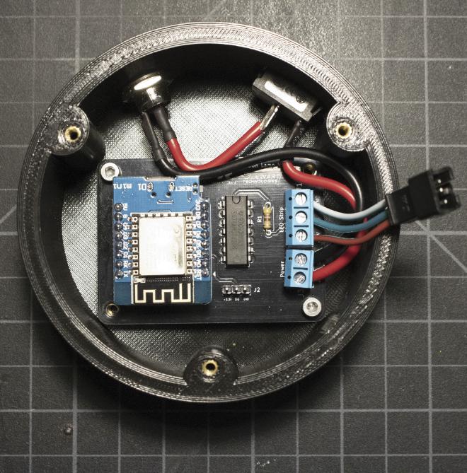
Assembled Electronics
Feed the wires for the touch button through the top of the LED stand and plug the button and strip into the PCB.
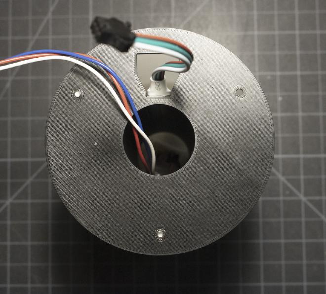
Touch Button Wire Routing
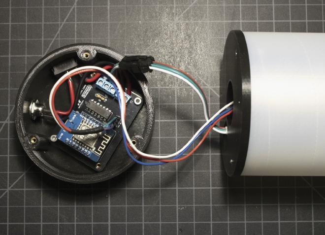
Carefully stuff the wires into the bottom stand and secure the LED stand to it with 3 M3 screws (you should be able to move the transparent cover enough to reach the screw holes). And finally, press-fit the cover into the slot on the LED stand.
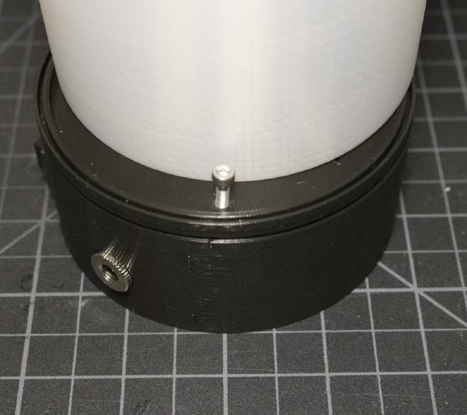
Screw Locations
And just like that, the Emotion Lamp is complete! I hope you enjoyed the build guide, let me know if you have questions or comments about the Emotion Lamp. You can leave a comment on the YouTube video linked above.
Parts List #
- PLA Filament - https://www.amazon.com/dp/B00J0ECR5I
- Transparent PLA Filament - https://www.amazon.com/3D-Solutech-Filament-Dimensional-Accuracy/dp/B00MB3CV6K
- Wemos D1 Mini - https://www.amazon.com/MakerFocus-NodeMcu-Development-ESP8266-Compatible/dp/B07KW54YSK
- M3 Heat Set Inserts - https://www.amazon.com/iplusmile-Embedment-Threaded-Printing-Projects/dp/B087NBYF65
- 5V 4A Power Supply - https://www.adafruit.com/product/1466
- SN74AHCT125N Level Shifter - https://www.adafruit.com/product/1787
- WS2812B LED Strip 1m 60 pixels/m- https://www.amazon.com/gp/product/B01CDTE9UC
- TTP223 Capacitive Touch Button - https://www.amazon.com/gp/product/B01LWKFS7L
- DC 5.5mm x 2.1mm Power Jack - https://www.amazon.com/Maxmoral-Connector-Waterproof-Threaded-Mounting/dp/B07S5ZLFDG
- SPST 6A/125V Power Switch - https://www.amazon.com/gp/product/B01N2U8PK0

